Table of Contents
A logic gate is a basic or fundamental building block of a digital circuit. Generally we discuss logic gates having two inputs and one output. At any instant, every terminal has one of the two binary conditions low (0) or high (1), representing voltage levels.
In most logic gates, the low state is approximately zero volts (0 V), while the high state is approximately positive five volts (+5 V). In logic gates we get output in Boolean either true (1) or false (0).
There are two types of logic circuits one is combinational and other is sequential logic circuit
In digital circuit theory, sequential logic is a type of logic circuit whose output depends not only on the present value of its input signals but on the sequence of past inputs. While, combinational logic devices are those whose output depends only on present input. So logic gates are combinational logic devices.
THERE ARE 7 LOGIC GATES WRITTEN BELOW
- AND gate
- OR gate
- NOT gate
NAND & NOR are Universal Logic gates because any Boolean function (all logic gates) can be implemented without need of other gate types.
- NAND gate
- NOR gate
Exclusive Logic gates
- X-OR gate
- X-NOR gate
BASIC LOGIC GATES
AND GATE
The AND operation in Boolean algebra is similar to the multiplication in ordinary algebra. The output Y is “True” (1) (HIGH) when both the inputs (A & B) are “True” (1) (HIGH). Otherwise, the output is “False” (0) (LOW). To understand it more clearlu check the truth table for two input AND gate. Symbol of AND gate shown below –
Symbol AND Gate

Truth Table for Two Input AND Gate
| INPUT | Output of AND Gate | |
|---|---|---|
| A | B | Y = A . B |
| 0 | 0 | 0 |
| 0 | 1 | 0 |
| 1 | 0 | 0 |
| 1 | 1 | 1 |
FOR EXAMPLE

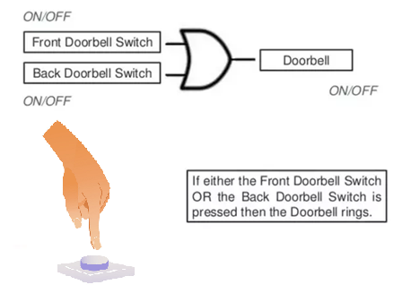
OR GATE
The OR operation in Boolean algebra is similar to the addition in ordinary algebra. The output Y is “True” (1) (HIGH) when either of the inputs (A or B) or both the inputs are “True” (1) (HIGH). If both the inputs are “False” (0) (LOW), only then the output Y is False (0) (LOW). To understand it more clearly check the truth table for two input OR gate. Symbol of OR gate shown below –
Symbol OR Gate

Truth Table for Two Input OR Gate
| INPUT | Output of OR Gate | |
|---|---|---|
| A | B | Y = A + B |
| 0 | 0 | 0 |
| 0 | 1 | 1 |
| 1 | 0 | 1 |
| 1 | 1 | 1 |
FOR EXAMPLE
NOT GATE
The NOT operation in Boolean algebra is nothing but complementation or inverse of logic. For logic 0 gives 1 and for 1 gives 0. This operation is indicated by a bar “–” over the input variable. Symbol of NOT gate shown below –
Symbol NOT Gate

Truth Table NOT Gate
| INPUT | Output of NOT Gate |
|---|---|
| A | Y = Ā |
| 0 | 1 |
| 1 | 0 |
UNIVERSAL LOGIC GATES
NAND GATE
The NAND gate – NOT gate in-front of AND gate operation makes NAND gate (N-AND). The output Y is “False” (0) (LOW) when both the inputs (A & B) are “True” (1) (HIGH). Otherwise, the output is “True” (1) (HIGH). To understand it more clearly check the truth table for two input AND gate. Symbol of AND gate shown below –
Symbol NAND Gate

Truth Table for Two Input NAND Gate
Comparison of NAND v/s AND gate
| INPUT | Output of NAND Gate | Output of AND Gate | |
|---|---|---|---|
| A | B | Y = A . B | A . B |
| 0 | 0 | 1 | 0 |
| 0 | 1 | 1 | 0 |
| 1 | 0 | 1 | 0 |
| 1 | 1 | 0 | 1 |
NOR GATE
The NOR gate – NOT gate in-front of OR gate operation makes NOR gate (N-OR). The output Y is “True” (1) (HIGH) when both the inputs (A & B) are “False” (0) (LOW). Otherwise, the output is “False” (0) (LOW). To understand it more clearly check the truth table for two input NOR gate. Symbol of NOR gate shown below –
Symbol NOR Gate

Truth Table for Two Input NOR Gate
Comparison of NOR v/s OR gate
A + B
INPUT Output of NOR Gate Output of OR Gate
A B Y = A + B
0 0 1 0
0 1 0 1
1 0 0 1
1 1 0 1
EXCLUSIVE LOGIC GATES
XOR GATE
The XOR ( exclusive-OR ) gate acts in the same way as the logical “either/or.” The output is “True” (1) (HIGH) if either, but not both, of the inputs are “True” (1) (HIGH). The output is “False” (0) (LOW) if both inputs are “False” (0) (LOW) or if both inputs are “True” (1) (HIGH).
Another way: output is 1 if the inputs are different, but 0 if the inputs are the same.
Symbol XOR Gate

Truth Table for Two Input XOR Gate
| INPUT | Output of XOR Gate | |
|---|---|---|
| A | B | Y = A ⊕ B = A . B +A . B |
| 0 | 0 | 0 |
| 0 | 1 | 1 |
| 1 | 0 | 1 |
| 1 | 1 | 0 |
XNOR GATE
The XNOR (exclusive-NOR) gate is just a XOR gate followed by an inverter (NOT gate). Its output is “True” (1) (HIGH) if the inputs are the same, and “False” (0) (LOW) if the inputs are different.
Another way: output is 1 if the inputs are the same, but 0 if the inputs are different.
Symbol X-NOR Gate

Truth Table for Two Input X-NOR Gate
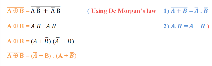
Using De Morgans’s Law A XNOR B
| INPUT | Output of XNOR Gate | Output of XOR Gate | |
|---|---|---|---|
| A | B | Y = A ⊕ B = (A +B ) . (A + B) | Y = A ⊕ B = A . B +A . B |
| 0 | 0 | 1 | 0 |
| 0 | 1 | 0 | 1 |
| 1 | 0 | 0 | 1 |
| 1 | 1 | 1 | 0 |
NEXT POST
POWER SOURCE
PREVIOUS POST
CMOS, ARDUINO, TTL LOGIC LEVELS