Table of Contents
LED – LIGHT EMITTING DIODE
LED – Light Emitting Diode is also a type of diode but how led gives us light when we power them up?
Answer is simple: Because LED’s are made up of compounds such as gallium arsenide (GaAs), gallium phosphide (GaP), or gallium arsenide phosphide (GaAsP) that posses light when they get excitation, while silicon and germanium does not do.

Now the one more question arises how they are of different colours like red, green, yellow and more?
When these compounds get excitation they emit photons of particular wavelengths depending on the making. If emitted photons have a wavelength of red colour in spectrum we can see red light, if photons have wavelength of green colour it appears to be green and so on.
Same as diode led works in one direction i.e. forward bias and having two terminals anode (+) and cathode (–).
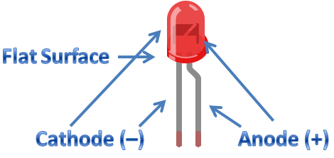
HOW TO FIND ANODE AND/OR CATHODE TERMINALS LIGHT EMITTING DIODE (LED)
- Most common anode (+) lead is longer than cathode (–)
- What if led legs were cut? When you look at the LED closely you find two metallic parts inside. One part is smaller than the other part, it is an LED anode (+) terminal.
- If the LED is not visible clearly inside then you will find a flat surface one of the sides of the LED this terminal is cathode (–).
TESTING OF LED
After you find the terminals then it is recommended to check if your LED is working or dead, because after making your complete project you find led is dead one will definitely annoy your mood.
First of all check the connectivity of the path. Take the multimeter rotate the knob at the diode symbol or sound symbol (which is also used for checking connectivity of path if) in the multimeter.
Now join the red and black wire (of multimeter) and you will hear a buzzer sound which shows yes connectivity is present. You can check it with two ends of wire, connected red and black terminals of multi-meter to different ends of wire you will hear buzzer sound.

With the same mode, now connect red wire to anode of LED and black wire to cathode of LED, this will light up the led & shows it is working but buzzer will not sound. If buzzer sounds in led this means your led is dead one.
CALCULATE RESISTANCE USING OHM’S LAW V=IR
When adding LEDs to a project, we need to consider the operating voltage and current. For example, common red LEDs require around 2.2 V and 5 to 20 mA of current.
Now this is the problem for us, because the output of the arduino is set 5 V and a much higher current. For this we can use a current-limiting resistor to reduce the current flow into an LED. But which value resistor do we use?
That’s where Ohm’s Law comes in. To calculate value of resistor for an LED or any load, use this formula:
R = (Vs − Vl) ÷ I
Where, Vs is the supply voltage (Arduino outputs 5 V), Vl is the load voltage drop (say, 2.2 V), and I is the current required for the LED (10 mA). (The value of I must be in amps, so 10 mA converts to 0.01 A.)
So, Vs is equal to 5 V, Vl is equal to 2.2 V and I equals to 0.01 A. Substituting these values into the formula gives a value for R of 280 Ω. However, the LEDs will also light up when fed current is less than 10 mA.
NOTE: In doubt, choose a slightly higher value resistor, because it’s better to have a less bright LED than a dead one!
THE OHM’S LAW TRIANGLE
Ohm’s Law states that the relationship between current, resistance, and voltage is as follows: voltage (V) = current (I) × resistance (R) If you know two of the quantities, then you can calculate the third. A popular way to remember Ohm’s Law is with a triangle, as shown in Figure

The Ohm’s Law triangle diagram is a convenient tool for calculating voltage, current, or resistance when two of the three values are known.
To find resistance cover up R and you left with V/R same like this to find voltage cover up V and you can see current times resistance.
As we learn how to calculate resistance we will now Light up an LED by the following circuit (both circuits are same)


NEXT POST
PULL UP RESISTOR AND PULL DOWN RESISTOR
PREVIOUS POST
PN JUNCTION DIODE AND VI CHARACTERISTICS