Table of Contents
In this tutorial section we will discuss about input and output signals of operational amplifier or OPAMP and OPAMP ICs which includes LM741 and LM358.
OPERATIONAL AMPLIFIER
Operational amplifier is a DC coupled high gain voltage amplifier with a differential input and whose output is several hundreds of times of its differential input. In simple terms, sensors give a low voltage output that cannot be easy to read, so an operational amplifier is used to amplify the signal.
Two commonly used opamp are LM741 & LM358. Difference between LM358 & LM741 is, LM358 is newer and have two OP-AMP on chip while in 741 only one OP-AMP is present. Both the IC’s have 8 pins.
In op-amp LM741 Offset is used because any sensor can give output without any input. To avoid noise signals we connect a variable resistor (POT-Potentiometer) in between +Offset and –Offset. Diagrams of the IC are shown below –
OPAMP LM 741 PINOUT
OPAMP LM358 IC PINOUT

OPAMP WORKING
Op-amp has two inputs namely inverting (–) and non-inverting (+) terminal and one output terminal.
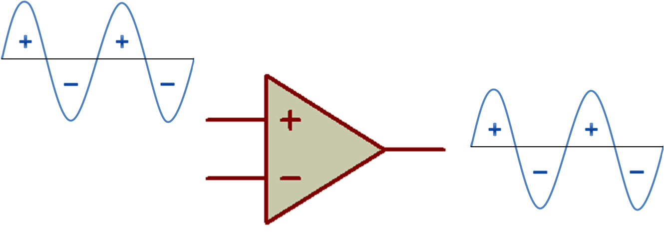
NON INVERTING (+) INPUT
If the signal is passed through the non-inverting (+) terminal of the op-amp then there would be no change in output signal.
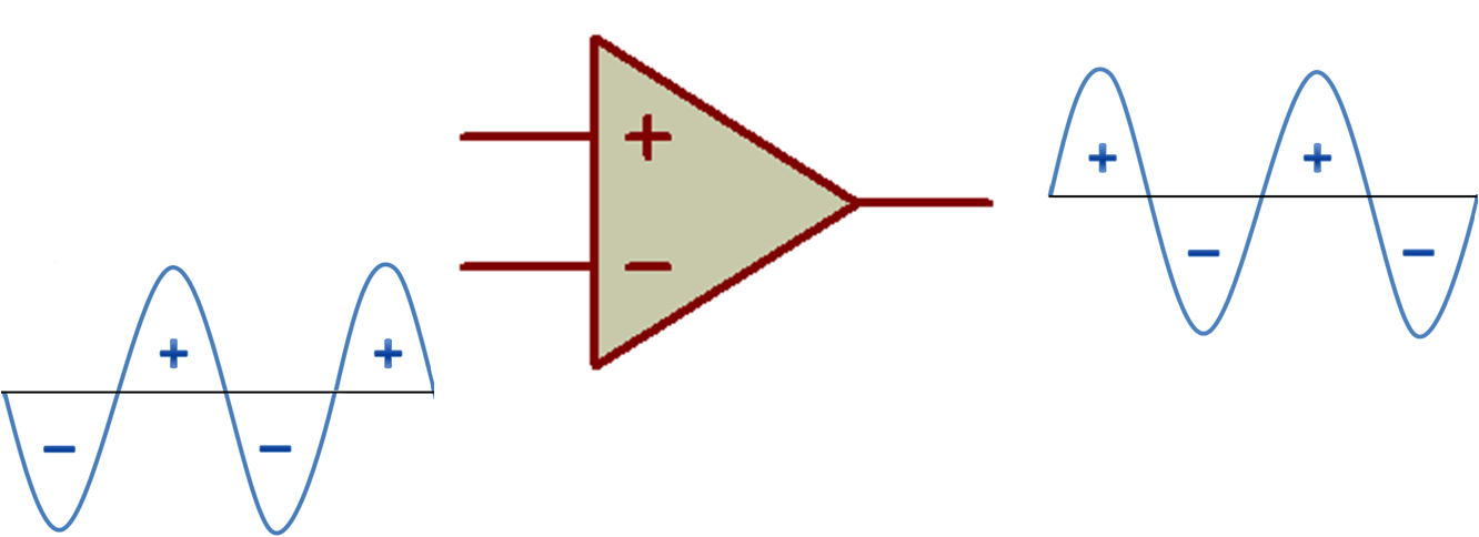
INVERTING (–) INPUT
If the signal is passed through the inverting (–) terminal of the op-amp then output signal will be inverted (just opposite). This is the same as the mathematical concept [+ multiply by number = number], [– multiply by number = – (number)].
As op-amp has differential input, this means it compares the strength of the input signals at inverting (–) and non-inverting (+) terminal which one is greater will be considered as input.
NEXT POST
LOGIC GATES USING SWITCH
PREVIOUS POST
TRANSFORMER
Good, simple and useful information well explained.