Table of Contents
You learn logic gates in the previous chapter. Now we will see how to design logic gates using switch. Circuit diagrams for logic gates are shown below –
LOGIC GATES USING SWITCH
AND GATE USING SWITCH
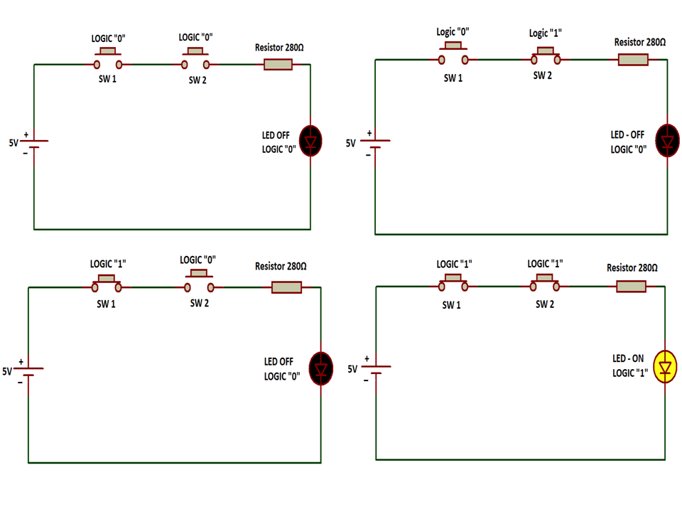
As we know 2 input AND gate needs, 2 input device, that’s why we are using 2 button (input device). And we need an output device that is LED. We connect buttons in series for AND Gate.
-
- So when both buttons are not pressed it means input logic is “0 and 0”, In that case LED will not glow.
- When any button is not pressed, the LED will not glow, it means the logic is “0 and 1” or “1 and 0”.
- Only when both buttons get pressed logic are “1 and 1”, LED will glow as seen in image below.
So we can say our circuit follows the AND gate truth table.
OR GATE USING SWITCH
Similarly, we know 2 input OR gate needs, 2 input devices, that’s why we are using 2 buttons (input device). And we need an output device that is LED. We connect buttons in parallel for OR Gate.
-
- Here, when both buttons are unpressed it means input logic is “0 and 0”, In that case LED will not glow.
- When any button is pressed, the LED will glow, it means the logic is “0 and 1” or “1 and 0”.
- And, when both buttons get pressed, the logic is “1 and 1”, the LED will glow as seen in the image below.
So we can say our circuit follows the OR gate truth table.

NOT GATE USING SWITCH
NOT gate is different from above gate in such a manner, we need only 1 input, that’s why we are using only 1 button (input device). And for output LED is used. We connect buttons in parallel for NOT Gate. NOT gate is also known as a logic inverter.
-
- Here, when you press the button it means input logic is “1”, In that case LED will not glow means output is logic “0”.
- And, when you don’t press the button it means input logic is “0”, In that case LED will glow means output is logic “1”.
Reason resistor connected before button because voltage needs to drop at some resistance to flow current. If we connect the resistor after the button then as you press the button the battery is short circuited.
So we can say our circuit follows the NOT gate truth table.

NEXT POST
LOGIC GATES USING TRANSISTOR
PREVIOUS POST
OPAMP OR OPERATIONAL AMPLIFIER
perfect and very comprehendable