Table of Contents
Earlier you see how to make Logic Gates using Switches and Symbols, Truth Table of Logic Gates. Now we see how to make logic gates using transistor.
One more interesting thing is IC’s are made of logic circuits and logic circuits are made up of logic gates, So basically IC’s have capacitors, resistor & transistors on chip for logical circuits, that’s why IC’s understand logic 1 & 0 as logic high and low only.
LOGIC GATES USING TRANSISTOR
Here we are using the transistor as a switch and controlling the base signal using a button so that we can control and see logic given to base.
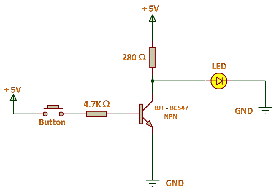
NOT GATE USING TRANSISTOR
NOT gate using transistor works similar as NOT gate using switch. We need 1 input device and 1 output device that are button and led respectively.
Initially when the button is open circuited, Transistor wouldn’t allow the signal to pass through the emitter. So the only path remaining for current to reach to the ground is collector i.e. through LED. In this case LED glows.
When we press the button it activates it’s base and maximum current passes through emitter rather than collector. In this case the LED does not glows.
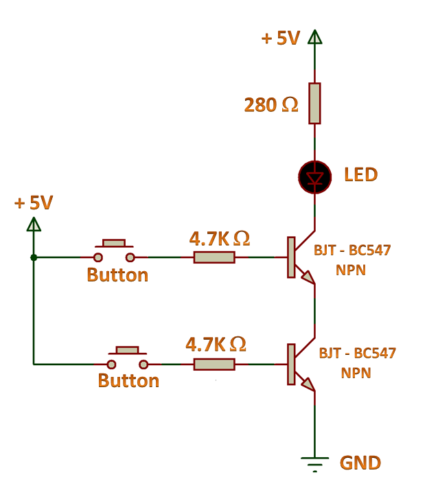
AND GATE USING TRANSISTOR
AND gate using transistor works similar as AND gate using switch. We need 2 inputs and 1 output device that are buttons and led respectively.
Switches are connected in series in AND Gate using switch, same as we connected the transistor in series, so that until both buttons are not closed, the LED will not glows.
OR GATE USING TRANSISTOR
OR gate using transistor works similar to OR gate using switch. We need 2 inputs and 1 output device that are buttons and led respectively.
Switches are connected in parallel in OR Gate using switch, same as it if we connect transistor in parallel, so that any one of the buttons get closed, LED will glows.

NEXT POST
5V POWER SUPPLY
PREVIOUS POST
LOGIC GATES USING SWITCH
Thanks for writing this up. I wanted an OR switch except I needed HIGH when off – ah I want a NAND, and so I use AND with a HIGH at rest from uProcessor pin and a momentary switch pulled high thru a limiting resistor and grounded when I press switch. Just need some de-bounce and I am good. I was using diodes until now, with a BC547 on the uP pin. But I can see now I can simplify using series BC547s. Many thanks.
It helped me a lot in my projects.
Thank you.