Table of Contents
LIGHT UP LED USING ARDUINO IN TINKERCAD
In the Arduino tutorial section, you already learn this topic but here we will light up led using Arduino in tinkercad platform.
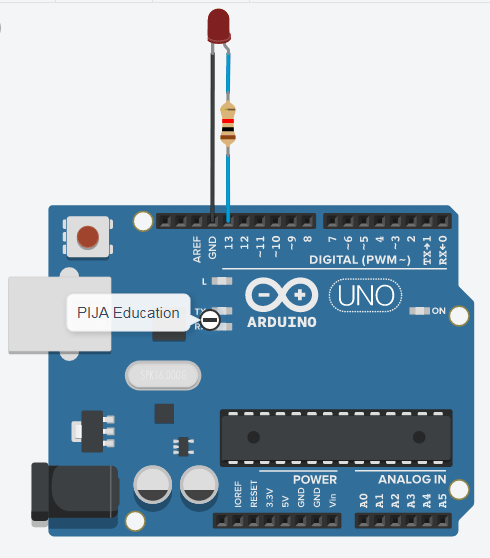
To light up an led you just need a DC power source (+5 V and ground terminal) here we connect LED anode terminal (+) to pin number 13 (digital IO) so that if we program our code as pin number 13 as HIGH (+5V), it behaves as power source and Cathode terminal (–) of led to the ground terminal of Arduino so that the circuit will get complete.
After uploading the program to Arduino, if we give power to Arduino Uno then it will light up the LED.
REQUIRED HARDWARE OR COMPONENT
| S.N. | Components | Quantity |
| 1. | Arduino Uno | 1 |
| 2. | LED | 1 |
| 3. | Resistor (280 ohm) | 1 |
| 4. | Connecting Wires | Few |
CIRCUIT DIAGRAM
CONNECTION TABLE TO LIGHT UP LED USING ARDUINO IN TINKERCAD
| S.N. | Arduino pin | LED Terminal |
| 1. | 13 | Anode (+) |
| 2. | GND | Cathode (–) |
CIRCUIT EXPLANATION
Here, The anode (+) and cathode (-) terminals of LED are connected to pin 13 and ground (GND) of Arduino Uno respectively and a resistor is placed between the LED anode terminal and pin number 13 which help us to limit the current and prevent LED from burning.
If we do not connect the resistor here we will get a message in software during simulation that “current through LED is 52.3 mA, while the recommended maximum is 20.0 mA”. The usable lifetime of the LED may reduce. That’s why there is a need for a resistor to reduce the current.
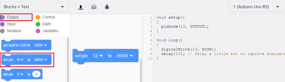
ARRANGEMENTS OF BLOCKS AND TEXT CODE PROGRAMMING FOR LED
From the Output section under ‘Blocks + Text’, drag and drop ‘set pin’ functional block to the workspace, and you will see code is automatically written there.
CODE BLOCKS AND TEXT CODE EXPLANATION
BLOCK EXPLANATION
Firstly select the output block. Drag set pin command from it and drop on scripting area (work area).
![]()
After that, click next to set pin and select 13 from the dropdown menu and then select HIGH and from the next dropdown menu which is a state, select HIGH or LOW means “1 and 0”, for digital pin 13. HIGH is required to glow an LED while LOW is required to turn it OFF.
![]()
TEXT CODE EXPLANATION
Every Arduino text program has two main functions: a setup() and a loop(). When we drag any blocks in the work area of concerned programming it can be seen setup() & loop() created automatically.
Step 1: In setup() function it automatically generates lines of code as soon as we select it on the set pin in blocks.
The Function “pinMode( )” has been defined here in the pin working mode as an input/output.
In this function, we have to pass two arguments –
- First one is pin number and
- Second is its mode, pinmode(pinNumber, mode).
In this we set pin number 13 as output: pinmode(13, OUTPUT).
void setup() {
  pinMode(13, OUTPUT);
}
Step 2: In the loop() function there is one in built function that is digitalWrite().
Function “digitalWrite()” is used to give HIGH(1) or LOW(0) state on a digital pin. Here, In the first line code of the loop, the digitalWrite() function is used to write HIGH (1) state (i.e. 5V) to digital pin 13.
In digitalWrite( ) function we also pass two argument –
- First one is pin number and
- Second is its state, digitalWrite(pinNumber, state).
In this we set pin number 13 output as HIGH: digitalWrite(13, HIGH).
void loop() {
  digitalWrite(13, HIGH);
}
START SIMULATION TO LIGHT UP LED USING ARDUINO IN TINKERCAD
Click on the start simulation button to perform the Light up LED program and to test the circuit.
[pad]
NEXT POST
LED BLINKING USING ARDUINO IN TINKERCAD
PREVIOUS POST
WHAT IS TINKERCAD?