Table of Contents
CODE BLOCKS FOR SWITCH AND LED INTERFACING WITH ARDUINO IN TINKERCAD
In this section of tutorial you will see code blocks for switch and led interfacing with arduino in tinkercad. This example will let you understand how to read digital inputs at digital IO pins of Arduino.
REQUIRED HARDWARE OR COMPONENT
| S.N. | COMPONENTS | QUANTITY |
| 1. | Arduino Uno | 1 |
| 2. | LED | 1 |
| 3. | Resistor 220 ohm | 1 |
| 4. | Resistor 10K ohm | 1 |
| 5. | Pushbutton | 1 |
| 6. | Connecting Wire | Few |
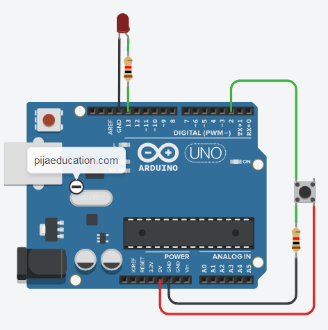
CIRCUIT DIAGRAM
CONNECTION TABLE FOR SWITCH AND LED INTERFACING WITH ARDUINO IN TINKERCAD
| S.N. | Arduino | LED | Pushbutton |
| 1. | 13 | Anode (+) | |
| 2. | GND | Cathode (–) | |
| 3. | 2 | Terminal 2a | |
| 4. | – | – | Terminal 1a |
| 4. | GND | Resistor to Terminal 2b | |
| 5. | 5v | Terminal 1b |
CIRCUIT EXPLANATION
In this circuit, we are going to take INPUT from a digital pin 2 using a push button and by using this we will control the LED which is connected as OUTPUT to the digital pin 13 of the Arduino.
INPUT CIRCUIT:
The pushbutton has four terminals namely 2a, 2b, 1a, 1b, where terminal 1a & 1b are internally connected or short circuited and similarly terminal 2a & 2b are connected. Pushbutton connected to arduino as follows
- Terminal 2a to pin 2 of Arduino
- Terminal 2b to one terminal of resistor, while resistor second terminal is connected to GND pin of arduino (a pulldown resistor is placed between the push button and ground terminal)
- Terminal 1a is not connected
- Terminal 1b is connected to 5 V of Arduino
Or simply you can use 2 terminal push button, this is the same circuit you need to follow

OUTPUT CIRCUIT
LED anode (+) and cathode (–) terminals are connected to the digital OUTPUT pin 13 and ground (GND) pin of Arduino Uno respectively and a resistor is placed between the LED anode terminal and pin number 13 which helps us to limit the current and prevent LED from burning it.
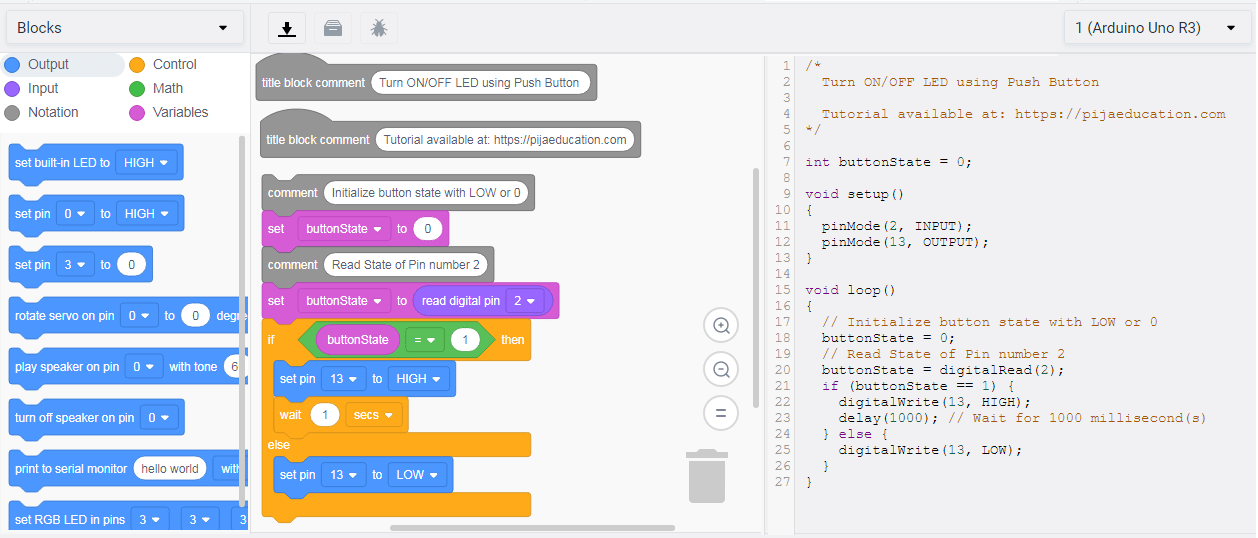
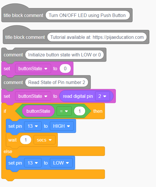
ARRANGEMENTS OF BLOCKS AND TEXT CODE PROGRAMMING FOR SWITCH AND LED INTERFACING
CODE BLOCKS AND TEXT CODE EXPLANATION
BLOCK EXPLANATION
Here, we have used the comment command block from the notation block menu for your better understanding. So let’s follow these steps
Step 1: In the first block we create a buttonState variable and drag the set buttonState command block from it and drop it at the work area.
![]()
After this go to the input block and drag read digital pin command block from it
![]()
and then drop into the first block at the place of 0 like this
![]()
Step 2: Then, go to the control block menu and drag the “if else” command block from it and drop it at the work area below the first block.

and now go to the math block and drag the second block from it
![]()
and drop it into hexagon shape “if” command

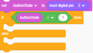
Step 3: Then again go to the variable blocks and drag buttonState block from it
![]()
and drop it on the first elliptical shape inside the math block in “if” command block and select ‘equal to’ sign from the pop-up menu.
Then, we will go to the output blocks and drag set pin command block
![]()
from it and drop under the “if” command block. After that, click set pin from 0 to 13 (the pin on which the LED is connected in the above circuit diagram) in the dropdown menu and select HIGH from the next dropdown menu.
![]()
Step 4: Now, select again set pin command block from it and drop it under the “else” command block.
After that, click set pin from 0 to 13 in the pop-up menu and select LOW from the next dropdown menu and below this select wait command block to wait to make the program wait for 1 second.
TEXT CODE EXPLANATION
- Declare a int variable buttonState which we will use to store input state of pin 2 (state: either HIGH ‘1’ or LOW ‘0’)
- In the setup function block, declare input and output pin of the Arduino which are 2 and 13 respectively using function pinMode. You need to pass two parameters in the pinMode function: first one is pin number, second one is its mode either INPUT or OUTPUT.
- In the loop function block,
- Set the value of variable buttonState to 0 or LOW before reading its state, this doesn’t make so much difference here but it is better to initialize the value.
- Now read pin 2 state using function digitalRead(pinNumber), this function requires one variable must be integer type, here pin 2 we are using and store its state in variable buttonState.
- Now check if the stored value is HIGH or LOW
- If HIGH, then turn ON LED connected at pin 13, using function digitalWrite(pinNumber, HIGH) and wait for 1 second
- If LOW, then turn OFF LED using the same function digitalWrite(pinNumber, LOW), but now the state will be LOW or ‘0’.
int buttonState = 0;

void setup()
{
  pinMode(2, INPUT);
  pinMode(13, OUTPUT);
}

void loop()
{
  // Initialize button state with LOW or 0
  buttonState = 0;
  // Read State of Pin number 2
  buttonState = digitalRead(2);
  if (buttonState == 1) {
    digitalWrite(13, HIGH);
    delay(1000); // Wait for 1000 millisecond(s)
  } else {
    digitalWrite(13, LOW);
  }
}
START SIMULATION
Click on the start simulation button to perform the pushbutton program and to test the circuit.

[pad]
NEXT POST
ULTRASONIC RANGE FINDER PROJECT WITH ARDUINO IN TINKERCAD
PREVIOUS POST
CODE BLOCKS FOR RGB LED INTERFACING WITH ARDUINO IN TINKERCAD