Table of Contents
Asynchronous communication is a type of serial communication, has a number of built-in rules that ensures robust and error free data transfers. These mechanisms, which we keep off for the external clock signal, are –
- BAUD RATE
- DATA FRAME
- Data bits / Data chunk
- Synchronization bits
- Parity bits
As there are many Asynchronous protocols for serial communication, it must be predefined that both the devices communicating on a serial bus are configured to use the exact same protocols.
Asynchronous communication is also used in Arduino, Communication protocol used in Arduino is UART (Universal Asynchronous Receiver Transmitter). Now let understand each step in detail
RULES FOR ASYNCHRONOUS COMMUNICATION
BAUD RATE IN ASYNCHRONOUS COMMUNICATION
Main element for speed in Asynchronous communication is baud rate. The baud rate defines how fast data is sent over a serial line. Unit of baud rate measures in bits-per-second (bps), means how many bits are transmitting or receiving per second. You can find out just how long it takes to transmit a single bit, if you invert the baud rate.
The only requirement is that both devices operate at the same baud rate. One of the most common baud rates, especially for simple stuff is 9600 bps. Moreover, other baud includes 1200, 2400, 4800, 19200, 38400, 57600, and 115200 etc.
Now obviously higher baud rate leads faster data transmission/reception, but in a limit. You usually won’t see baud rate speed exceeding 115200 (suppose), that is fast for most microcontrollers. Selecting too high baud rate gives you errors on the receiving end, as clocks and sampling periods just can’t keep up.
DATA FRAME
Each block of data transmitted or sent is actually a packet or frame of bits. Frames are created by appending (adding in previous) synchronization (start and stop bit) and parity bits to our data.

Let’s get into the details of each of these frame pieces.
DATA BITS OR DATA CHUNK
We ambiguously call this block of data a data chunk, because its size isn’t precisely specified. The amount of data in each packet can be between 5 to 9 bits. However, the standard data size is 8-bit byte, but other sizes have their importance and uses. Especially if you’re transmitting 7-bit ASCII characters, a 7-bit data chunk can be more efficient than an 8-bit data chunk.
After agreeing on a character-length, both communicating serial devices also have to agree on the endianness (termination of data bit) of their data. Is data sent as the most-significant bit (MSB) to least and least-significant bit (LSB) as first, or vice-versa? If it’s not stated, you can usually assume by-default that data is transferred as a least-significant bit (LSB) first.
SYNCHRONIZATION BITS
The synchronization bits are 2 or 3 special bits transferred with each data chunk or data packet or frame, known as the start bit and the stop bit(s).
As the name implies, start bit marks the beginning and must be one bit, while, stop bit(s) mark the end of a packet and configurable to either one or two bits (though it’s commonly left at one).
The start bit is always indicated by an idle data line going from 1 to 0, while the stop bit(s) will transition back to the idle state by holding the line at 1.
PARITY BITS
When a group of binary bits (words) is transmitted from one location to another, there may be some error introduced in the word and thus incorrect information is received. The error is caused because, 1 and 0 are transmitted as voltage high and low and due to noise any ‘1’ in the transmitted word may be changed into ‘0’ or vice versa.
For example, if you want to send (57)10 i.e. (110101)2 and because of an error receiver receives (100101)2. Due to error in second MSB received data is (37)10. Due to error in single ‘1’ we get incorrect data, to avoid these errors we error detecting or correcting codes, one of it is parity check.
The most common and simple method used in error detection is to add an additional bit, called the parity bit. Parity is a low-level error checking method.
There are two types of the parity bit
- Odd Parity: Total number of 1’s in the word including parity word must be an odd number
- Even Parity: Total number of 1’s in the word including parity word must be even number
Parity bit is normally added as MSB, To produce the parity bit, all 5-9 bits of the data byte are added up, and the evenness of the sum decides whether the bit is set or not.
For example, parity bit for 3-bit message shown in the table below:
| WORD | EVEN PARITY | ODD PARITY |
| 000 | 0 | 1 |
| 001 | 1 | 0 |
| 010 | 1 | 0 |
| 011 | 0 | 1 |
| 100 | 1 | 0 |
| 101 | 0 | 1 |
| 110 | 0 | 1 |
| 111 | 1 | 0 |
Parity is optional, and not very widely used because
- It requires both sender and receiver to implement error-handling (usually, received data that fails must be re-sent)
- It’ll also slow down your data transfer a bit
- It can be helpful for transmitting across noisy mediums
BAUD RATE 9600 8N1 (AN EXAMPLE)
In 9600 8N1(by default) – 9600 is the baud rate, 8 data bits are transmitting, no parity bit, and 1 stop bit is transmitting in a frame or data chunk, it is one of the usually used serial protocols. So, what would a packet or two packets of 9600 8N1 data look like? Let’s have an example!
A device transmitting the ASCII characters ‘A’ and ‘S’ would have to create two packets of data.
- The ASCII value of ‘A’ (uppercase) is 65, and the 8-bit binary value is 01000001,
- While the ASCII value of ‘S’ (uppercase) is 83, and the binary value is 01010011.
All that’s left is appending sync bits.
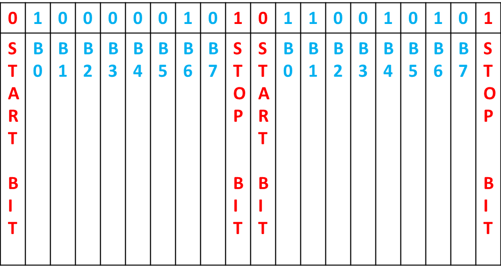
It is not stated, but it is assumed that data is transferred as LSB (least-significant bit) first.
As the transfer rate is 9600 bps, the time consumed for each of those bits either high or low is 1/(9600 bps) or 104 µs per bit.
So we can see every packet has 8 bits data and 10 bits to be transferred including start and stop bit, now we can say, we are actually sending 960 bytes of data per second (9600 / 10 = 960).
Now that’s about serial packet generation and transmitting, now move on to the hardware section.
WIRING AND HARDWARE
A serial bus comprises of just two wires – one for sending data and another for receiving. That’s why serial devices should have two serial pins: the receiver, RX, and the transmitter, TX.

There is a point where beginners make mistakes, let’s understand it. First you need to make a common ground by connecting both devices ground, then as you can see RX of device 1 connected to TX of device 2 and vice versa. Because, for example, if a person is speaking (mouth as a transmitter) i.e. transmitting and another person is listening (ears as a receiver) i.e. receiving information this makes sense. What if both are speaking and no one is ready to listen will this make a proper communication? Of course not.
Some serial buses have just a single connection between sending and receiving. For example, EM18 RFID reader, it only sends data to the microcontroller that’s why in this only TX pin (mouth) is available it has no any RX serial pin. In this case, just connect TX of RFID to Rx of microcontroller or microcontroller based devices or development board like Arduino.
HARDWARE IMPLEMENTATION
We’ve learned asynchronous serial from a theoretical side, wires connection required for communication between serial devices. Now let’s see how this happens at the signal level (voltage level). The most popular hardware implementation techniques are TTL (Transistor-Transistor-Logic) and RS232.
TTL and RS232 are differed by following, TTL Logic level works between 0V to 5V while,
RS232 works at a maximum open-circuit voltage of 25 Volts, signals level of ±5 V, ±10 V, ±12 V, and ±15 V are commonly seen.
Table below shows the signal level indication for different voltage levels for both TTL and RS232
| TTL | 0 V | +5 V |
| Start Bit Data Bit of value 0 |
Stop Bit Data Bit of value 1 Idle Line |
|
| RS232 | -12 V | +12 V |
| Stop Bit Data Bit of value 1 Idle Line |
Start Bit Data Bit of value 0 |
Signal at VCC level i.e. +5V indicates either an idle line, a bit of value 1, or a stop bit
and at 0V (GND) signal represents either a start bit or a data bit of value 0.

RS-232s found in some computers and peripherals. RS-232 signals generally range between –12V and + 12V.
- In this, low voltage (-5V to -12V) indicates idle line, a stop bit, or a data bit of value 1.
- A high voltage RS-232 signal means either a start bit, or a 0-value data bit. That’s kind of the opposite of TTL serial.

TTL is easier to implement in comparison to RS232 and its series like Rs485 etc. while RS232, RS485 etc. are complex but better suited for long range data transmission.
Now let explore the tool, microcontrollers use to convert their data on a parallel bus to and from a serial interface. That is UARTs!
READ NEXT
UART – UNIVERSAL ASYNCHRONOUS RECEIVER TRANSMITTER