Table of Contents
An infrared sensor is an electronic module which is used to sense certain physical appearance of its surroundings by either emitting and/or detecting infrared radiation. IR sensors are also capable of determining the heat being emitted by an object and detecting motion. Now lets learn the interfacing of IR Sensor and Arduino.
IR SENSOR WORKING:
Here we are using an IR sensor for detecting obstacles. IR transmitter transmits IR signal, as that signal detects any obstacle in its path, the transmitted IR signal reflects back from the obstacle and received by the receiver.
This is similar to the topic Interface of Switch as an input to Arduino board and gets output, but here we replace the switch with an IR sensor. This is like an automatic switch which gives signal on obstacle detection.
PINOUT:
- VCC: 3.3V-5V power input pin
- GND: 0V power pin
- OUT: Digital Output Pin

TECHNICAL SPECIFICATION/RATING
- Operating Voltage: 3.0V – 6.0V
- Current: at 3.3V : ~23 mA & at 5.0V: ~43 mA
REQUIRED HARDWARE
| S.No. | Item | Quantity |
| 1 | Arduino Uno | 1 |
| 2 | Breadboard | 1 |
| 3 | IR Sensor | 1 |
| 4 | LED | 1 |
| 5 | Resistor 220 ohm | 1 |
| 6 | Male to Male jumper | 5 |
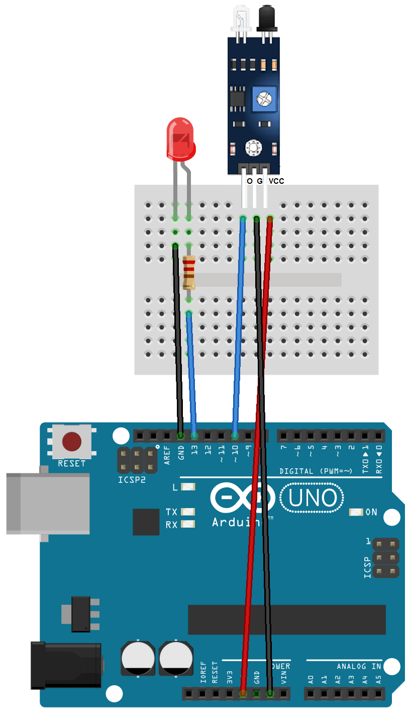
BUILDING CIRCUIT IR SENSOR AND ARDUINO
Here we connected Pins describe below
| Arduino pin | LED |
| 13 | Anode (+) |
| GND | Cathode (-) |
| Arduino pin | IR Sensor |
| VCC | VCC |
| GND | GND |
| 10 | OUTPUT (O) |
Make circuit connection as shown
IR SENSOR ARDUINO CODE
int LEDpin = 13;
int obstaclePin = 10;
int hasObstacle = LOW;  // LOW MEANS NO OBSTACLE

void setup() {
  pinMode(LEDpin, OUTPUT);
  pinMode(obstaclePin, INPUT);
  Serial.begin(9600);
}

void loop() {
  hasObstacle = digitalRead(obstaclePin);

  if (hasObstacle == HIGH) {
    Serial.println("Stop something is ahead!!");
    digitalWrite(LEDpin, HIGH);
  }
  else {
    Serial.println("Path is clear");
    digitalWrite(LEDpin, LOW);
  }
  delay(200);
}
IR SENSOR ARDUINO CODE EXPLANATION
Here we define an integer type variable LED and assign 13 to it. Then we define another integer type variable obstaclePin and assign 10 to it. Then we define another variable hasObstacle and set its state to LOW (0), this is used for the reading status of pin number 7 of the arduino. Status either LOW or HIGH means is obstacle present then HIGH if not then LOW.
int LEDpin = 13;
int obstaclePin = 10;
int hasObstacle = LOW;  // LOW MEANS NO OBSTACLE
Now in void setup(), define pin-mode that is LED as output and obstaclePin as input means where we use term LED it is 13 there and where we use obstaclePin it is 10 there. Then for serial communication we are setting a baud rate of 9600 by using the function Serial.begin(). We will discuss baud rate and serial communication in a later chapter (Communication System).
void setup() {
  pinMode(LEDpin, OUTPUT);
  pinMode(obstaclePin, INPUT);
  Serial.begin(9600);
}
In void loop(), first we are reading obstaclePin(10) state is it either HIGH or LOW, as we connected IR sensor over there, as IR sensor detects any obstacle by transmitting and receiving waves it gives a HIGH signal which in turn sets obstaclePin(10) of arduino to HIGH and If the sensor does not detect any obstacle it gives a LOW signal which in turn sets obstaclePin(10) of arduino to LOW. This signal will be stored in variable hasObstacle. So there are two conditions for hasObstacle either HIGH or LOW.
Then we will check it in ‘if block’, if it is HIGH, if condition matched then we print a message on the serial monitor “Stop something is ahead!” & Turn LED on by doing LEDpin(13) HIGH.
Otherwise the signal will LOW, so in ‘else block’ we print a message on the serial monitor “Path is clear”& Turns LED off.
This complete cycle will be delayed by 200 milliseconds or 0.2 seconds.
void loop() {
  hasObstacle = digitalRead(obstaclePin);

  if (hasObstacle == HIGH) {
    Serial.println("Stop something is ahead!!");
    digitalWrite(LEDpin, HIGH);
  }
  else {
    Serial.println("Path is clear");
    digitalWrite(LEDpin, LOW);
  }
  delay(200);
}
OUTPUT
As an obstacle will be detected a message will print on the serial monitor & LED turned ON and if there is no obstacle detected, LED will be turned OFF.
READ NEXT
TEMPERATURE SENSOR AND ARDUINO
great content