Table of Contents
Let now understand the working principle and relay working with some circuitry. In this tutorial, we connected two LEDs on two switching positions of relay that are NO and NC see in pin configuration.
RELAY WORKING
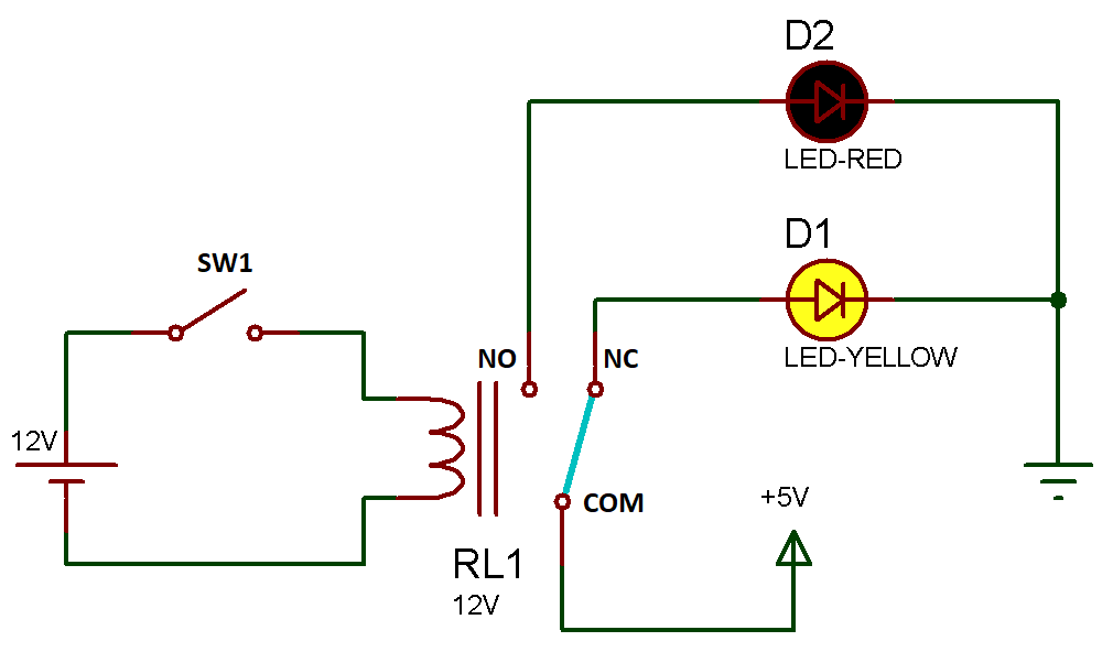
One led (LED-Yellow) is connected to the NC terminal and the other led (LED-Red) is connected to NO terminal.
When the coil is not energized, the COM terminal is connected to the NC terminal. This is the normal condition of relay.
So what is happening here is (see diagram), because the switch (SW1) is open-circuited there is no electrical signal provided to the relay for now, so the relay remains in its normal position. A source of +5V is connected (source that is required to drive the load (LED)) on the COM terminal that I required to drive a led and COM is short-circuited to NC terminal this makes the path complete and yellow led glows.
The Coil terminals control the switching. When voltage is applied across the coil it becomes an electromagnet (rating of relay depends on the coil and that much input must be required across the coil to work properly). Its core attracts the switch armature (lever) and activates the switch (switching it to NO contact point).
When the coil is energized, the COM terminal will connect to the NO terminal, as shown in the image.
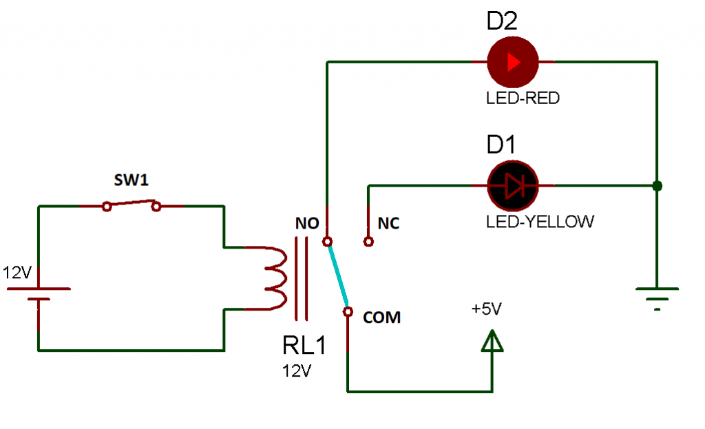
Now as we press the switch and make the circuit short-circuited an electrical signal attracts the lever of COM towards the coil and now COM will be short-circuited with NO terminal and the supply from the COM is directly received by the Red led which glows red LED and yellow LED will be turned off.
Few Examples of relay circuits:
EXAMPLE 1
If I do not need a yellow LED in the circuit, I can simply remove it from the circuit then if the relay coil is not-energized nothing will happen to the circuit means no led glows and if the relay coil is energized then red LED will be turned on.


EXAMPLE 2
And if I remove the red LED from the circuit then if the relay coil is energized then the yellow LED will be turned off.


The Normally Open Terminal (NO), Normally Closed Terminal (NC) and Common Terminal (COM), make up the switch contacts. How they’ll be connected depends on the application.