Table of Contents
ANALOG TO DIGITAL CONVERSION – ADC IN ARDUINO
Here we are using Arduino UNO as a microcontroller board and want to read analog pin input in volts [0 – 5 V] or milli-volts [0 – 5000 mV] and to give digital output (0 to 1023, depends upon microcontroller resolution). So let’s see how to convert analog to digital conversion (ADC in Arduino) for any microcontroller.
ADC IN ARDUINO
Before getting started let’s see an analog to digital conversion example and what values we are getting from the Analog pin.
-
- When Arduino get 0 V on the Analog input it gives Digital output 0
- When Arduino gets 2.5 V on the Analog input it gives Digital output 511
- When Arduino gets 5 V on the Analog input it gives Digital output 1023
- When Arduino gets 6 V on the Analog input it gives Digital output 1023, same as 5 V
This means at any Analog input (voltage) it gives digital output, so we don’t need to convert Analog to Digital but we need to find what Analog input was for the corresponding Digital output.
And if the applied voltage is more than its maximum input (5V), like 6 V it gives us the same value as of 5 V that is 1023. Because it depends upon the resolution of the ADC chip.

In Arduino, we have an ADC converter chip inbuilt in the microcontroller ATMEGA328. This ADC is a 10-bit converter.
Now, Maximum Input Voltage at the controller’s Analog pin can be 5 V i.e. 5000 mV.
What is “n” bit-resolution? It means, it can have 2n values and the maximum number is 2n – 1.
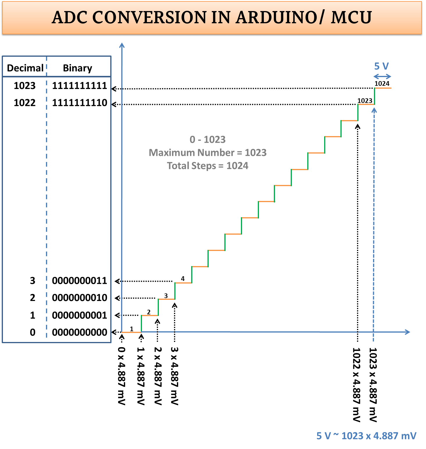
Because of 10-bit resolution, we can get the maximum value 210 i.e. 1024, and range will be “0 to 210 – 1 i.e. 1023” in the decimal number system. Here is Analog to Digital conversion concept
We know, 5 V = 5000 mV and if we divide it by the maximum possible number i.e. 1023 then we get (5000 mV / 1023) = 4.887 (approx.) as the step size. So if we multiply 1023 with 4.887 (1023 * 4.887) we get 5000 mV (approx) that is the input.
In simple terms
-
- If the input voltage is 0 to 4.887 mV the output will be 0 in digital values by the ADC converter chip.
- Between 4.887 x 1 to 4.887 x 2 output will be 1.
- Between 4.887 x 2 to 4.887 x 3 output will be 2.
- And so on.
ADC FORMULA
ANALOG VOLTAGE = ADC VALUE * STEP SIZE
ADC CONVERSION ARDUINO CODE
We will get ADC value from the function analogRead(pin); which is between 0 – 1023.
// Tutorial: https://pijaeducation.com/adc-in-arduino/
int dValue, analogInputV;
void setup() {
  Serial.begin(9600);
}
void loop() {
  dValue = analogRead(A0);
  Serial.print("Digital value: ");
  Serial.print(dValue);

  analogInputV = dValue * 4.887;
  Serial.print(" , Analog Input voltage: ");
  Serial.print(analogInputV);
  Serial.println(" mV");

  delay(1000);
}
Serial.print (dValue); will print digital value that is already converted in digital by ADC converter ranges between 0 to 1023, But it is not the input voltage at analog pin.
If the input is maximum i.e. 5 V (5000 mV) then the digital value will be 1023 by the controller. So, if the output is 1023 then multiply it by 4.887 (5000/1023 = 4.887) to get Analog Voltage
1023 * 4.887 = 5000
So, the dValue = 5000 is in mV.
or You can use map function in Arduino IDE for preciseness like this
MAP FUNCTION
// Tutorial: https://pijaeducation.com/adc-in-arduino/
int dValue, analogInputV;
void setup() {
  Serial.begin(9600);
}
void loop() {
  dValue = analogRead(A0);

  analogInputV = map(dValue, 0, 1023, 0, 5000);
  Serial.print(" , Analog Input voltage: ");
  Serial.print(analogInputV);
  Serial.println(" mV");

  delay(1000);
}
Map function does some mathematical computing and returns a value. Computations like assign input range and map them to take output in other ranges.
For example, I want to map marks of a student into percentage. If the maximum marks are 1000 then its input range is 0-1000 and the percentage will be the output so its range will be 0-100.
Map function requires 5 parameters.
-
- 1st variable name which value to be computed, here student marks
- 2nd variable is lower bound of input range i.e. 0 (marks 0-1000)
- 3rd variable is upper bound of input range i.e. 1000 (marks 0-1000)
- 4th variable is lower bound of output range i.e. 0 (percentage 0-100)
- 5th variable is the upper bound of input range i.e. 100 (percentage 0-100)
In simple terms, if the number of a student is 400, it will give us 40 as output which we can consider as a percentage.
ADC IN NODEMCU or ADC IN ESP8266
Resolution is 10 bit
Range 0 – 1023
So, Total Steps are 210 = 1024
Operating Voltage = 3.3 V or 3300 mV
Step size = 3300 / 1023 = 3.2258
-
- If ADC value is 0 then voltage is 0 * 3.2258 = 0 mV
- If ADC value is 10 then voltage is 10 * 3.2258 = 32.258 mV
- If ADC value is 100 then voltage is 100 * 3.2258 = 322.58 mV
- If ADC value is 1023 then voltage is 1023 * 3.2258 = 3299.99 mV
NOW LET GO FOR THE TEMPERATURE SENSOR LM35
TEMPERATURE SENSOR CALIBRATION FOR ARDUINO
In the LM35 temperature sensor, 10 mV denotes 1 degree centigrade. So if the voltage value divided by 10 it will give us output in degree centigrade.
int a = analogRead(A0);
a = a * 4.887;
temperature = a / 10;
TEMPERATURE SENSOR CALIBRATION FOR NODEMCU
In the LM35 temperature sensor, 10 mV denotes 1 degree centigrade. So if the voltage value divided by 10 it will give us output in degree centigrade.
int a = analogRead(A0);
a = a * 3.2235;
temperature = a / 10;
NOW LET SAY WE HAVE INPUT OF MORE THAN 5V
Suppose 20 V, which means we can not give the output directly to the controller so will use the basic electronics concept Voltage Divider rule.

‘R1 is 3K’ and ‘R2 is 1K’. So, Vin max can be 20V and Vout can be 5V. Vout should not exceed the operating voltage that is 5V for Arduino. Now we have output voltage on controller input that can be calibrated using the above concept.
Basically, we have Vout value on our controller analog pin and need to find Vin using voltage divider formula:
Vout = Vin (R2/R1+R2)
Vin = Vout (R1+R2) / R2
//actual Analog to digital converted Value OR Digital Value
int a = analogRead(A0);
// actual Analog Value OR Input Voltage at A0
Vout = a * 4.887;
// actual source voltage
Vin = a * (3000 + 1000) / 1000;
READ POST
SOIL SENSOR WITH ARDUINO IN ANALOG MODE